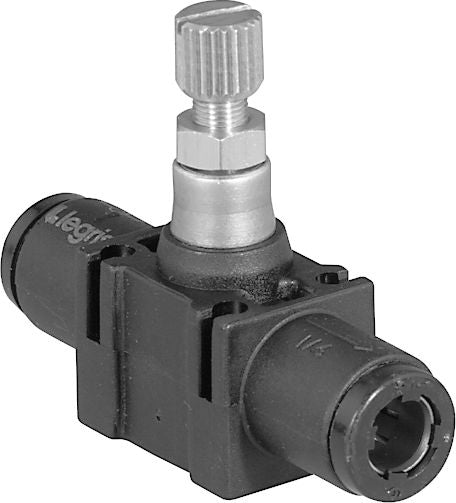
Inline 1-Way Flow Control Regulator 10 x 10mm
(Pack of
1.0)
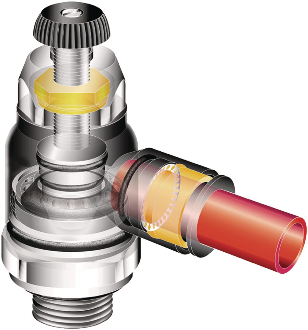
In-Line Flow Control Regulators can be easily added to existing circuitry. Simply splice it into the cylinder port line. They may be used individually or, they may be stacked together using two joining clips, supplied with each valve. Panel mounting is accomplished by using the through holes in the molded body. Adjustment CharacteristicsControl is achieved gradually due to the extreme sensitivity of the adjustment screw, which allows exceptionally fine setting levels. With the use of a locking nut, the in-line flow control may be secured in its final setting. Settings are maintained even under adverse conditions such as vibration. A captive adjustment screw prevents loss or dangerous blow out. Full Flow In Both Directions Intake capacity is always slightly greater than the full open exhaust capacity, enabling maximum variation of speeds between outward and return strokes. Designed To Be VersatileLegris in-line flow controls are unidirectional flow control valves. Intake air flows freely through the flow control; exhaust air is metered out through a specially designed adjustment screw. An arrow on the body of the valve indicates the direction of controlled flow.
• Working temperature: 30°F to +160°F
• Working pressure: 15 to 145 PSI
• Sutable fluids: Compressed air
• Construction:
– Body: Glass-reinforced nylon 6.6 or brass
– Gripping ring: Stainless steel
– Adjustment screw: Nickel-plated brass
– Locking nut: Nickel-plated brass
– Base: Nickel-plated brass with thread sealant on tapered components
Photos are representations of product.
CAUTION: These fitting systems are not D.O.T. approved. Do not use for air brake connections.
Couldn't load pickup availability
California Proposition 65: WARNING: Cancer and Reproductive Harm -
www.P65Warnings.ca.gov
Catalog page#: 9-37
Frequently Bought Together
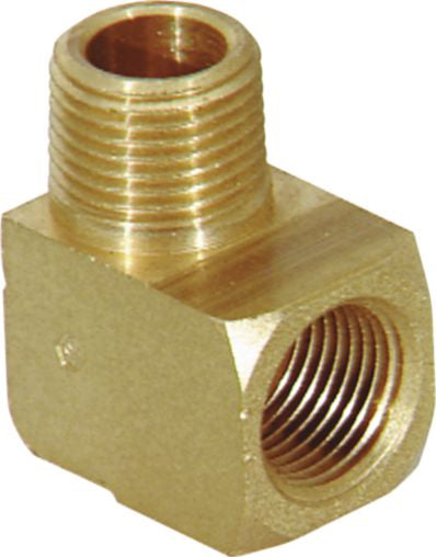
Pipe Street Elbow Brass 90° 3/8-18 x 3/8-18
Couldn't load pickup availability
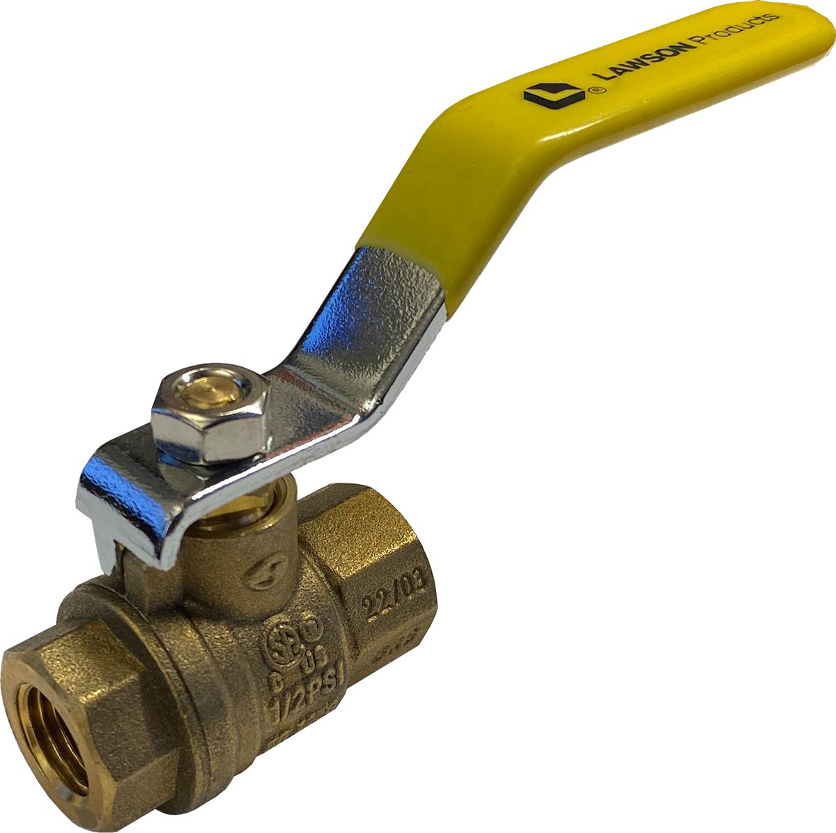
Forged Body Ball Valve Brass 1/2-14 x 1/2-14
Couldn't load pickup availability
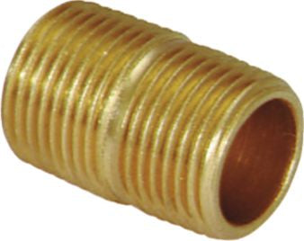
Pipe Close Nipple Brass 1/2-14 x 1/2-14
Couldn't load pickup availability
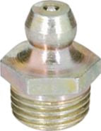
Ball Check Grease Fitting Straight
Couldn't load pickup availability
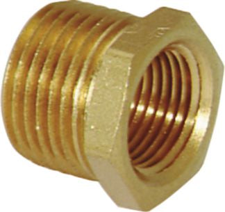
Pipe Bushing Brass 3/8-18 x 1/4-18
Couldn't load pickup availability
Super 77 Miniature Hose Clamp SS 7/32 to 5/8"
Couldn't load pickup availability
Push-to-Connect Union Nylon 5/32 x 5/32"
Couldn't load pickup availability
Push-to-Connect Elbow Nylon 1/4 x 1/4"
Couldn't load pickup availability
Push-to-Connect Connector Brass 5/16 x 1/4"
Couldn't load pickup availability
Butt Connector 16 to 14 AWG Blue
Couldn't load pickup availability
USS Flat Washer Thru-Hardened Steel 1/4"
Couldn't load pickup availability
USS Flat Washer Thru-Hardened Steel 3/8"
Couldn't load pickup availability
Product Description
In-Line Flow Control Regulators can be easily added to existing circuitry. Simply splice it into the cylinder port line. They may be used individually or, they may be stacked together using two joining clips, supplied with each valve. Panel mounting is accomplished by using the through holes in the molded body. Adjustment CharacteristicsControl is achieved gradually due to the extreme sensitivity of the adjustment screw, which allows exceptionally fine setting levels. With the use of a locking nut, the in-line flow control may be secured in its final setting. Settings are maintained even under adverse conditions such as vibration. A captive adjustment screw prevents loss or dangerous blow out. Full Flow In Both Directions Intake capacity is always slightly greater than the full open exhaust capacity, enabling maximum variation of speeds between outward and return strokes. Designed To Be VersatileLegris in-line flow controls are unidirectional flow control valves. Intake air flows freely through the flow control; exhaust air is metered out through a specially designed adjustment screw. An arrow on the body of the valve indicates the direction of controlled flow.• Working temperature: 30°F to +160°F
• Working pressure: 15 to 145 PSI
• Sutable fluids: Compressed air
• Construction:
– Body: Glass-reinforced nylon 6.6 or brass
– Gripping ring: Stainless steel
– Adjustment screw: Nickel-plated brass
– Locking nut: Nickel-plated brass
– Base: Nickel-plated brass with thread sealant on tapered components
Photos are representations of product.
CAUTION: These fitting systems are not D.O.T. approved. Do not use for air brake connections.
Technical Specifications
| Item#: | 62252 |
|---|---|
| Style | Flow Control Regulator |
| Configuration | In-Line One-Way |
| Tube Size | 10 mm |
| Material | Nylon |
| Wrench Size | 14 mm |
| Working Pressure | 15 to 145 PSI |
| Temperature Range | 30 to 160 °F |
| UNSPSC #: | 40183100 |
| TAA Compliant: | No |
| Weight: | 0.25 lb |
Product Restrictions
California Proposition 65: WARNING: Cancer and Reproductive Harm -
www.P65Warnings.ca.gov